Digital outputs are all fun and good, but very few things in actual reality are digital (just “on” or “off”) in nature. MCUs have a few ways to emulate a truly analog output, with Digital to Analog Converters (DACs) being the most useful one. However, in most cases, we can make due with a digital signal driven in a specific manner. This is where PWM comes in.
Generating a PWM, For a LED
PWM stands for “Pulse Width Modulation”. We will be generating a series of pulses, and modulating, changing, the width of those pulses over time. This allows us to do all kinds of fun things in the real world, for example, drive DC motors or dim LEDs.
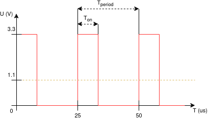
The waveform of a typical PWM signal would look something like this:
The waveform has some key properties:
- Tperiod is the time of a full ON-OFF cycle, this is usually static per application,
- TON is the time during which the output pin outputs a HIGH signal (in the STM32 case, a 3.3 V signal).
Not pictured is the frequency (FPWM) of the PWM signal. This can be derived from the Tperiod: FPWM = 1 s / Tperiod. For, example, if our Tperiod = 25 us, then the frequency FPWM = 1 s / 25 us = 40 kHz.
The other property that’s not pictured is the duty cycle (D) of the pulse. The duty cycle represents the ratio between the ON and OFF time in a single period: D = TON / Tperiod. In the figure above, if we continue with the assumption that Tperiod = 25 us, then we can say that TON = 8.3 us, and thus D = 8.3 / 25 = 0.33 = 33%. The duty cycle is the metric that we will be driving by modifying the TON of the signal.
An important property of the PWM signal is that, once the frequency of the signal is high enough, in most physical systems, the ON-OFF switching will be evened out by the properties of the connected circuitry. This means that the observed output voltage UOUT can be expressed as the function: UOUT = UVCC × D. Note that UVCC is the peak voltage of the signal, in our case, 3.3 V. So for our drawing, the averaged output voltage of the PWM signal is: UOUT = 3.3 × 0.33 ~= 1.1 V.
Timers
Generating a PWM signal on the STM32 series is done via the timer peripheral. In other cases, these may be called counters, or timer/counters. But in principle, across microcontroller series and manufacturers, timers work the same: they count the number of pulses, and thus, allow you to keep track of time.
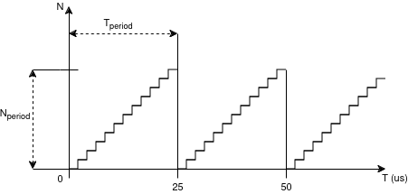
A timer is effectively configured to run at a given frequency, and it will count. It will either count to its maximum limit (either unsigned 32-bit or 16-bit integer’s maximum value for STM32s), or until it reaches a configured Nperiod value. Once that value is reached, usually, the timer is reset and it will either stop or restart, depending on the configuration. The functionality of a generic timer is illustrated in the figure below.
As can be seen, by modifying the Nperiod value, we can modify the real world Tperiod in which the timer counts to its reset value.
The rate at which the timer counts is determined by Ftick. For STM32s, the timers are powered by APB1 and APB2 clocks. These usually have speeds in the megahertz. Which can be way too big. For this purpose, timers on the STM32 include a frequency divisor: a prescaler. This prescaler value will let us slow down the counting to a reasonable point for us. As such, we can say that Ftick = Fin / Nprescale.
This also lets us calculate the Fperiod = Ftick / Nperiod = Fin / Nprescale / Nperiod. And if we remember that Fperiod = 1 s / Tperiod, we can calculate the period time as well. From the above example, we can say that Fperiod = FPWM.
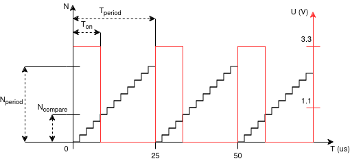
This lets us tie the period of the PWM to the period of the timer. But we also need a midway point for inverting the signal. STM32 timers call this value a “compare” value: it’s an arbitrary value during which we can do something in. For generating a PWM, the STM32 hardware uses the compare value as the point at which the the pulse inverts its value. This means, we can combine the two previous figures as follows:
Configuring a Timer
We now know that we need to configure a timer to generate PWM. Great.
From before, we know that we also have to choose two parameters: Nprescale and Nperiod. What you choose as Nperiod will dictate the range in which you can adjust the PWM “value” in code. For example, setting a period of 100 will let you input the PWM “power” as a number between 0 and 100. Setting it to some other, more random value, will make the logic harder. So, pick a sane period. In our case, 100 will do.
We thus know that Nperiod = 100 and we also know that Fin = 8 MHz and we wish our output frequency to be FPWM = 40 kHz. This lets us calculate Nprescale as the last unknown in our configuration.
If FPWM = Fin / Nprescale / Nperiod
then Nprescale = Fin / FPWM / Nperiod
thus Nprescale = 8e6 / 40e3 / 1e2 = 2.
Note: due to the digital nature of our work, and with the number 0 counting as a “1” for mathematical purposes, both Nperiod and Nprescale will need to be input as the calculate value - 1. So we’re finally left with:
Nperiod = 99, and Nprescaler = 1.
Now we go over into CubeMX. For illustration purposes, we’ll be applying the PWM to the LED that’s on the dev board. This will have the effect of letting us dim the LED’s brightness. Fortunately, the STM32F303k8 dev board has a PWM channel attached to the LED pin PB3. We can check this by clicking the pin and seeing if there’s any TIMx_CHy functions attached to it. In the case of PB3, we can see that there’s TIM2_CH2, which means it’s connected to Timer 2’s channel 2.
Our next step is to enable TIM2 by setting its “Clock Source” to “Internal Clock”, and setting “Channel2” to “PWM Generation CH2”.
With that done, we now have to set the counter values. We have to set:
- Prescaler (PSC - 16 bits value) to our calculated Nprescale (1),
- Counter Period (AutoReload Register - 32 bits value) to Nperiod (99),
- set auto-reload preload to “Enabled”.
With this done, generate the code as you would normally.
Controlling the PWM
We’ve configured the timer, the PWM output, now to start it and play with its duty cycle.
After code generation, we go to main. The first thing we have to do is actually start the timer and start the PWM generation. This is done as such:
  /* USER CODE BEGIN 2 */
  HAL_TIM_Base_Start(&htim2);
  HAL_TIM_PWM_Start(&htim2, TIM_CHANNEL_2);
  /* USER CODE END 2 */
The code should be placed in user code section 2, before the while loop but after the MX_x_Init functions.
HAL_TIM_Base_Start(&htimx)will start the actual timer itself, andHAL_TIM_PWM_Start(&htimx, TIM_CHANNEL_y)will start the PWM for that timer on the specified channel.
If you’re using multiple PWM channels from the same timer, you will have to call HAL_TIM_PWM_Start for each
channel that you’re using.
To set the PWM to a given duty cycle value, we would use the macro function __HAL_TIM_SET_COMPARE(&htimx, TIM_CHANNEL_y, n).
Where the n is a value between 0 and Nperiod. This effectively sets us our duty cycle as well.
To dim the LED from off to full brightness in sequence, we could do something like this, for example:
  /* Infinite loop */
  /* USER CODE BEGIN WHILE */
  while (1)
  {
	__HAL_TIM_SET_COMPARE(&htim2, TIM_CHANNEL_2, 0);
    HAL_Delay(400);
	__HAL_TIM_SET_COMPARE(&htim2, TIM_CHANNEL_2, 20);
    HAL_Delay(400);
	__HAL_TIM_SET_COMPARE(&htim2, TIM_CHANNEL_2, 40);
    HAL_Delay(400);
	__HAL_TIM_SET_COMPARE(&htim2, TIM_CHANNEL_2, 60);
    HAL_Delay(400);
	__HAL_TIM_SET_COMPARE(&htim2, TIM_CHANNEL_2, 80);
    HAL_Delay(400);
	__HAL_TIM_SET_COMPARE(&htim2, TIM_CHANNEL_2, 99); // because our period was 99 and not 100.
    HAL_Delay(400);
    /* USER CODE END WHILE */

    /* USER CODE BEGIN 3 */
  }
  /* USER CODE END 3 */
Bootload the code, and off we go. We now have a functional PWM useful for dimming a LED… Or driving motors. Which we’ll cover next.


